imc CANSAS-IGN: Ignition Timing Measurement

Self contained ignition angle, time, and speed measurement module with CAN-Bus output
The imc CANSAS-IGN ignition timing measurement module is a compact measurement unit which provides universally compatible CAN-Bus outputs of RPM and per-cylinder ignition timing for any spark-ignited engine up to 12 cylinders.
- CAN-Bus output of all processed signals
- High speed transient signal capture in "Snapshot mode" with transfer of buffered signals via CAN-Bus
- Cylinder recognition determines which piston(s) fire based on a camshaft position sensor
- High sampling rate and high resolution for even the highest RPM engines
To learn more, click on the tabs below...
Integrable, Adaptable, Fast

Particularly now in the age of hybrid vehicles, efficient and environmentally friendly combustion engines are assuming a central role in the development program of every leading automotive manufacturer. So it's no wonder that many car companies and their suppliers and service providers are again intensively developing the science of internal combustion engines.
To date, measurements of ignition angle required elaborate combustion analysis equipment. These dedicated analyzers, while quite capable in their own right, generally lack methods for easily integrating into existing test systems.
The compact and economical imc CANSAS-IGN overcomes these hurdles:
...with high speed:
imc CANSAS-IGN captures a signal's crossing through defined thresholds at a resolution of a fraction of microseconds. From this, the ignition angle can be calculated with a high precision of 0.1 degree of the crankshaft, up to 20,000 RPM. The module has a sampling rate of 3 MS/s.
...with ease of integration:
From test stands to mobile applications—imc CANSAS-IGN is simple to integrate into virtually any existing test environments due to its configurable CAN-Bus outputs.
...with its adaptability:
Results can be recorded by any CAN data acquisition system, and combined and compared with other measurement data.
Four isolated inputs are provided for connecting the ignition signal (SPARK), crankshaft rotation pulse (ANGLE), absolute angle reference signal (REF), and the camshaft position signal (CAM). With 3 MSamples/second inputs, the imc CANSAS-IGN module processes all signals with software selectable settings and outputs RPM and timing angle for each cylinder via configurable CAN-Bus outputs.
To aid in setup and diagnostic work, the imc CANSAS-IGN module also includes a high speed transient “snapshot” mode to capture the high speed signal envelope, buffer and transfer it to the data logger via the CAN-Bus interface.
And thanks to the built-in display, the imc CANSAS-IGN module can also be used as a high-speed assistant for investigating the ignition angle, even when data logging isn’t required.
How does imc CANSAS-IGN work?
Based on a high speed measurement of the ignition signal, crankshaft rotation pulse, and optional absolute angle reference signal, and camshaft position signal, ignition angle and engine RPM can be simultaneously computed and transferred via CAN-Bus or as voltage signal.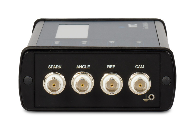
All input signals are isolated and fully conditioned (low-pass, AC coupled, including individually selectable signal level and hysteresis.
Ignition Signal
Supports a variety of ignition signal detection methods, including ignition clamp, both primary and secondary coil taps, and logic level signals.
Crankshaft Signal
Several available measurement points may be used for engine speed, sincluding the engine's own inductive pickup sensors, external Hall effect sensor or encoder, as well as logic level signals.
Index Channel
The "zero" or "index" pulse input for use when the relative TDC position is indicated by a separate logic-level signal.
Camshaft Position
An optional logic-level signal for use in determining which cylinder is firing for each ignition pulse. Up to 4 cylinders may be specifically selected for individual evaluation.
Thus, the results of the high speed ignition angle measurement and engine RPM can be easily recorded via any CAN-Bus equipped data logger, such as the imc BUSDAQ or more full featured
imc CRONOSflex.
Using the included imc CANSAS software and any compatible PC-to-CAN interface, the imc CANSAS-IGN may be user configured for a wide range of input signal combinations. This includes angle determination from a missing tooth (if appropriate), conditioning of the threshold, edge and hysteresis, and filter properties necessary for a variety of ignition and crankshaft/camshaft signal electrical standards. With a sampling rate of 3 MS/s, imc CANSAS-IGN may be used with even high RPM engines.
Cylinder Specific Measurements
With help of the camshaft position signal, the ignition signal common to all cylinders may be used for cylinder specific firing angle determination. For up to 4 cylinders (user selectable which cylinders on engines of greater than 4 cylinders), imc CANSAS-IGN will transmit a running min, max, and average ignition angle.
Configuration Stored Onboard
Since the imc CANSAS-IGN stores its configuration in internal flash memory, you have the added advantages of being able to use the module for diagnostic work without a PC, as well as pre-configuring the module for use by colleagues.
When a more detailed look is needed

Although normal operation would process the high sample rate down to a rate manageable for a long duration measurement, the Snapshot Mode allows the imc CANSAS-IGN to provide a view of the original high speed input signals, but without the need for extra high speed equipment. In this mode, the module takes a snapshot of the input signal at a high data rate, buffers it and transfers via the CAN-Bus at a slower rate for vieweing in your CAN-Bus data logger.
With the Snapshot Mode you...
- Obtain precise signal information
- Can check the signal level to configure the thresholds
- Can check the signal level to configure high pass and low pass filter
This snapshot eliminates the need for extra high speed equipment (e.g. an oscilloscope) when selecting appropriate signal levels for detecting signal edges. But it also enables the user to investigate the effects of pre-processing techniques such as smoothing filters, AC coupling, etc.