
Measuring currents with extreme dynamics using auto-ranging technology
Measuring range from 50 nA to 50 A
In the development and testing of devices and components with DC or battery supply, the examination and monitoring of operating currents is a very important topic. Anyone who measures currents that are determined by sophisticated power management, sleep modes, various operating modes and their transitions is faced with extreme dynamics that take conventional measurement technology to its limits. Auto-ranging offers new possibilities, but also new challenges.
Dynamic auto-ranging during active measurement
The high-resolution ADC technology used across the board in measurement technology already allows considerable dynamic ranges to be covered with a fixed scale design. Despite that, sensors, signals and the physical processes to be examined often encompass such wide spans that an adapted range selection (for example through pre-amplification) is necessary in order to get the maximum use from the technology.
Whereas the range is fixed before the test in classic methods, auto-ranging methods enable dynamic adaptation during the running measurement. This is useful if one doesn't know the expected course or if the test covers the entire dynamic range and should also completely record it.
If one wishes to attain range dynamics that extend far beyond the ADC resolution (24-bit, for example), one can dynamically increase the gain, at least in the case of voltage measurements. For current sensing with a shunt resistor however, the task is more demanding: it is necessary here to adapt the shunt during the measurement – without interrupting the measuring circuit or adversely affecting the continuous measurement in the transition area.
A typical application scenario is, for instance, a single continuous test measurement that analyses a complete power-up cycle: From tiny leakage current in sleep mode, through surge and inrush at the start, to high-power work areas – and back again. In addition, the measurement technology must be non-reactive. Therefore, it may not affect the test object and should provide optimum data resolution and accuracy in all work areas. There is of course a great need for this in the automotive sector, for instance in a test field that examines a large variety of components and control devices from a vehicle and their complex interplay in the on-board electrical system. Moreover, the development and testing of mobile devices with battery and wireless technology and even energy harvesting are faced with similar tasks.
What can current measuring with auto-ranging achieve?
Where?
- Extreme range dynamics (full-power vs. sleep-mode)
- Power-Up tests of components and systems
- Demarcated work areas/operating points
- Limited use for periodic signals
How?
- Dynamic range adjustment during active measurement
- Continuous data acquisition
- No interruption in the load circuit (non-reactive)
Current measurement: a special challenge
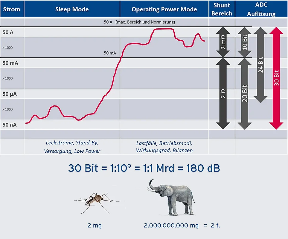
When measuring currents, the choice of the sensing shunt resistor represents a crucial decision and also a limitation. While it must be large enough to supply significant voltage signals that aren't drowned out by noise and disturbance variables, the power dissipation that increases by the square of operating current imposes hard limits. For a desired maximum working current (measuring range) of 50 A, the selected shunt may not be greater than 2 mΩ, because it is then already dissipating 5 W – the limit for a device if it is still to be handy. At this upper operating point it supplies a scanty 100 mV which, however, is still well manageable and can be processed cleanly after adequate pre-amplification, for instance by means of a 1 V ADC with 24-bit resolution. However, if one desires at the same time a measurement resolution of 50 nA with this configuration in order, for instance, to assess leakage currents, it soon becomes clear that the limits of physics are well exceeded here. Signals of 2 mΩ × 50 nA = 0.1 nV definitely have no chance to prevail over noise and parasitic thermovoltages, etc., even if they were to be “inflated” with an additional gain of, for example a factor of 1000, yielding 0.1 μV (Figure 1a). The gain must therefore be generated from the shunt itself.
That can be implemented by a second serial shunt as shown in fig. 1 b: This shunt's resistance of 2 Ω is increased by a factor of 1000 (shunt gain), but is only active at low currents. It is dynamically bypassed as soon as higher working currents threaten to overload it.


Figure 1c outlines how, with this combination, a total range dynamics of about 30 bits can be achieved, i.e., a ratio of maximum measuring range to minimum resolution of 1:1 billion (10^9). For comparison: using a balance with the corresponding range dynamics, you could measure a mosquito weighing 2 mg and then an elephant weighing 2 tons (= 2 × 10^9 mg).
Thus, the basic principle is already outlined:
The heart of the measuring module from imc is formed by the measuring current path, in which a low-impedance 2 mΩ shunt designed for the maximum current is always active. A second, high-impedance 2 Ω shunt in series can still cleanly capture even the smallest currents, but is dynamically bypassed by means of fast switches as soon as the present working current exceeds a threshold of around 100 mA. The voltages across both shunts are measured by a 30 kS/s ADC with 24-bit resolution and correctly selected, scaled and calibrated by a processor. Output data is delivered via CAN-bus with selectable data rates of between 1 Hz and 1 kHz. Output variables, apart from mean values, are also minimum and maximum values within the selected output interval. These are derived on the basis of the internal data rate of 30 kHz.
Switching dynamics:
The switching of the shunt must take place much faster than is necessary for the actual measurement: Suddenly increasing current must instantaneously short-circuit the high-impedance shunt in order not only to prevent it from burning up, but also to avoid a load-voltage peak in the load circuit. As an (albeit transient) voltage drop in the load circuit, this would influence or even disconnect the load components to the tested.
Therefore, the activation of the shunt bypass is controlled by a fast comparator, but renewed activation of the high-impedance shunt is only permitted with a delay (fig. 2). The combination of level hysteresis (switching threshold) with the temporal hysteresis of the fast activation (< 1 µs) and slower deactivation (< 1 ms) of the bypass guarantees safe and stable state transitions.


Thus, it is also possible in the case of increases in current (inrush, surge) of 10 A/µs to realize virtually non-reactive switching that limits voltage drops across the load to about 400 mV. An appropriate capacitance across the shunt also helps to flatten the voltage transients in the transition zone until the comparator reacts (fig. 3). The concept is thus also suitable for measuring test objects with a highly dynamic behavior, such as switching regulators, LED drivers, etc.

The hysteresis dead times, as well as the settling times of the parallel measurement paths (ADC) that have to be masked out, limit the meaningful measuring data output rates to 100 Hz. However, it is also possible to disable the auto-range shunt switching in a "fixed mode", and then to use a maximum data rate of 1 kHz.
A rapid and reversible MOSFET-based electronic fuse guarantees safety in all cases and disconnects the current path in case of overload.
Universally usable CAN module:

This auto-ranging concept is implemented as a universally usable CAN bus measuring module for use in laboratories and test benches. In the form of the imc CANSAS-IHR (fig. 4) in a sturdy aluminum profile housing, it combines two independent, electrically isolated auto-range measuring paths for the measurement of current through loads supplied with up to 18 V (DC). Isolation allows the measuring point to be placed anywhere: supply or return conductor (high side / low side), partial or total currents.
In addition to the digital signal processing and control, the meticulous thermal design of the system is of particular importance. The enormous currents are to be routed carefully in the PCB layout via the components such as the connection technology, power shunt and FET switch that have to be properly cooled. The precision shunt is one of the most critical components here: a symmetrical heat flux must ensure that parasitic thermocouples do not cause increased errors and drifts at junctions and must minimize the effects of self-heating.
imc CANSAS-IHR high-resolution current measurement module
- Isolated current measurement with shunts
- Test objects: loads of up to 18V DC
- 2 shunts with dynamically switching current path (bypass) at high current flow
- Automatic and dynamic range selection: auto-ranging
- Resulting 30 bit range-dynamics: 50 nA - 50A
- Acquisition and output of average and min/max
- Output selectable at intervals of 1 Hz/10 Hz/100 Hz, internal processing/acquisition with 30 kHz
- Data rate with a static measuring range (50A, without auto-ranging) up to 1 kHz
When is auto-ranging useful?
Basically, auto-ranging methods are helpful in particular in the applications described here, which concern separated work areas that are traversed in succession and in which one also remains (fig. 5). Then use can actually be made of the fact that small signals are processed optimally with low noise and adapted gain, resulting in a real gain in usable measurement resolution.
However, auto-ranging is not a cure-all that will necessarily be of advantage in any measurement situation. In the case of periodic signals, for instance, which are spectrally analyzed by means of FFT, the following should be borne in mind: If the inner part of the signal range, i.e. the fine measurement range of small amplitudes, is ideally resolved with adaptive gain (for example, g = 1000), then this low-noise level is also effective only in a comparably small portion of the total time, namely 1/1000 (fig. 6). The influence on the background noise (noise floor) of the FFT, which is still dominated by the signal-to-noise ratio (SNR) of the coarse measuring range, is therefore correspondingly negligible.
A further essential prerequisite for auto-ranging is that the fine or zoomed range must be zero-symmetric. The extended signal to be resolved must therefore lie around the zero point of the unipolar or bipolar signal range, because we are not concerned here with AC coupling, but with an adapted linear pre-gain. While that is the case for this type of current measurement, it does not apply in quite different applications such as bridge measurements using strain gauges, because in that case the signal is typically afflicted by a large initial offset that needs to be compensated.

