Step-by-step instructions for assembling the ring stator.
Note: for instructions and further details see the manual
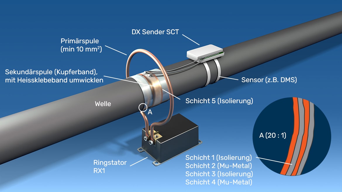
Basic overall structure of the telemetry system with ring stator
The picture shows the basic overall structure of the telemetry system with ring stator and the individual layers of the secondary winding.
Step 1
Wrap the shaft with fabric tape. The insulated surface must be wider on both sides than the Mu metal to be subsequently applied to prevent short-circuiting of the Mu metal with the shaft.
Step 2
The individual components of the mounting set.
Step 3
Calculate the length of the mu-metal with the formula π * diameter + 10 mm. For the diameter, include the previously applied insulating layer.
Step 4
Cut the first layer of mu-metal with protective film to the required length.
Step 5
Apply an overlapping black insulating tape to one end of the Mu metal.
Pull off the protective foil and stick the mu metal onto the shaft. The ends must not touch, there must be no short-circuit winding with the mu metal.
Step 6
Now insulate the Mu metal as described under 1.
Step 7
Now calculate the length of the second mu-metal layer using the formula π * diameter + 10 mm.
Step 8
Cut the second Mu metal layer to this length.
Step 9
Attach an overlapping black insulating tape to one end of the mu-metal. Pull off the protective foil.
Now apply the second mu-metal layer. The overlap of this mu-metal layer must be offset by at least 90 ° to the overlap of the first mu-metal layer. So, for example, rotate the shaft by at least 90 ° before applying the second mu-metal layer.
Step 10
Apply the first layer of heat-resistant Kapton tape (polyimide tape) in the center.
Step 11
Calculate the length of the copper tape for the secondary winding using the formula π * diameter - 5 mm.
Step 12
Cut the copper tape to size.
Step 13
Tin both ends of the copper strip.
Step 14
Now attach the Dx-SCT transmitter unit in a suitable manner.
Step 15
Measure and cut the stranded wire (at least AWG 20 or 0.62 mm2) for the inductive power supply, strip the ends and tin them. Solder one stranded wire each with a maximum length of 100 mm onto the copper strip ends. The connecting leads should be soldered as flat as possible to the copper strip. As drawn in Figure 36, the leads must be aligned at right angles to the copper strip.
Step 16
Now place the copper strip as secondary winding centrally on the polyimide layer. The distance between the copper ends must be approx. 5 mm.
The soldering points with the stranded wire must not touch each other. The strands must be flat and close together. They must not touch the stator when the shaft is rotated.
The sensor leads should not cross with the connecting leads.
For measurements on shafts with high speed or high temperature, imc offers special solutions (half shells, special housings, etc.)
Step 17
Solder the wire ends to the IP1 and IP2 terminals of the Dx-SCT transmitter unit.
Step 18
To secure against centrifugal forces and for protection, the transformer winding must be wrapped with the supplied fabric tape.
Step 19
Calculate the length of the copper ring: (40 mm + diameter) * π + 2 * L
Step 20
Shape the copper wire: Bend the ends and form a bow.
Step 21
Press the copper tube together at both ends.
Step 22
Drill a 5 mm diameter hole in each end of the copper tube.
Step 24
Important: Sand the contact surfaces of the copper tube to reduce resistance.
Step 25
Screw the primary winding to the ring stator.
Step 26
Important: Set the output power regulator to the minimum position by turning it counterclockwise to avoid overvoltage.
Step 27
Connect the supply cable to the ring stator.
Step 28
Connect the supply cable to the ring stator.